


")
SpaceX’s Starlink Project, which seeks to create satellite internet access unfettered by ground installation limitations, has attracted the attention of the United States military. Drawn to the project due to its potential for greatly enhancing battlefield communications, the Pentagon has already roped in SpaceX for preliminary tests under a US Air Force Research Laboratory (AFRL) programme called ‘Global Lightning’ where Starlink has sought to be integrated into the US military’s emerging next-generation sensor—shooter networks. As such, it would be worthwhile to take a deeper dive into how Starlink is intended to work and evaluate its true military potential.
Overview
As part of the Starlink Project, SpaceX plans to eventually deploy a constellation of around 42,000 small satellites weighing around 260 kg each in Low Earth Orbit (LEO) using its Falcon 9 rocket. In the event of a Starlink satellite malfunctioning, its on-board propulsion system will be used to deorbit the spacecraft over the course of a few months. In the unlikely scenario of the propulsion system of the satellite becoming inoperable, it would burn up in Earth’s atmosphere within one to five years. The satellites use data from the debris tracking system of the US Department of Defense (DoD) i.e. the Pentagon to autonomously maneuver and avoid the space debris. Each satellite has a flat-panel design with four phased array antennas and a single solar array. The onboard star tracker navigation system (based on SpaceX’s dragon) is used for precision pointing and the krypton thrusters are used for attitude control and altitude maintenance so as to keep the satellite optimally oriented for providing uninterrupted internet.
Now, the US Federal Communications Commission has authorized SpaceX to operate Starlink satellites broadcasting in the Ku, Ka and V-band frequencies, with groups of spacecraft positioned at different altitudes and various planes in LEO. The project has become a major business for SpaceX, which is competing with companies like Amazon’s Project Kuiper and OneWeb to deploy fleets of thousands of small satellites in LEO to beam broadband internet signals from space to users around the world. As an aside, astronomers have repeatedly red-flagged the Starlink Project because of the “nightsky illumination” caused by it, although SpaceX has vowed to reduce and ultimately remove the illumination issue altogether.
Exercises by the US Military involving Starlink
The US DOD’s first exercise involving Starlink was conducted in 2019 yielded mixed results. As part of a major new wave of tests, the Pentagon and SpaceX together intended to conduct a ‘live fire’ exercise in the month of April 2020. However, due to Corona Crisis the April exercise has been postponed to September 2020.
Be that as it may, US Air Force (USAF) Acquisition Chief William Roper had told the press in February 2020 that the now postponed April Exercise would see SpaceX Starlink satellites link up with multiple armed forces systems in a ‘massive’ live fire exercise. The demonstration would have involved shooting down a drone and a cruise missile and various parts of the overall exercise were to be simultaneously conducted at several different sites including the Marine Corps Air Station Yuma in Arizona as well as Eglin Air Force Base in Florida. The tests would have also tied in ground forces, submarines, ships, and a variety of space-based assets.
Nevertheless, the tests, now scheduled for September, will actually be part of a larger test of the Pentagon’s Advanced Battle Management System (ABMS), a new communications ecosystem designed to enable Joint All-Domain Command and Control (JADC2), which will allow U.S. forces and allies to coordinate military operations in real-time across all domains, such as sea, land, air, space and cyber operations. Back in February 2020, Roper said that his ‘hope for this event, unlike the first event, is that we have an equal measure of things that fail for things that succeeded’, and that ‘We’ve come so far in ABMS that we realize that it’s bigger than just replacing the capability that JSTARS provides,’. He also stated that ‘If you get ABMS right, you’ve just built the military’s ‘internet of things.’ That’s super exciting.’
Notably, during a less extensive test last year, Starlink satellites were reportedly connected with an AC-130 gunship. Also, Starlink is being seen as a means for the F-35 and F-22 to stealthily exchange data. Despite the two jets having advanced “sensor fusion” capabilities, the US Air Force’s (USAF’s) two most advanced fighters can’t really talk to each other. The F-35 uses the Multifunction Advanced Data Link (MADL) to securely share sensitive information with other F-35s and the F-22 has its own data link, the Intra-Flight Data Link (IFDL).
How Starlink is supposed to work
Meanwhile, a 2019 theoretical study done by the University of Birmingham on Passive radar using Starlink transmissions set to certain standard parameters revealed the possibility of using Starlink satellite emissions as an illuminating source for bistatic real and synthetic aperture radars, assuming a receiver on or near the earth’s surface.[1] The emphasis was on power budget and detection range, which forms the backbone of any radar system. The power budget for detection is the aforementioned analysis is similar to the previous work done on GNSS-based radar.[2] [Please look at references i & ii for further details of the technical sections that follow & the images & tables enclosed therein]
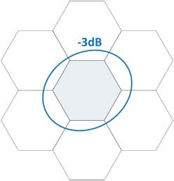
It is believed that Starlink will create the equivalent of a surface cellular structure similar to mobile telephony networks, with satellite antenna beams replacing terrestrial cellular towers. This is to be achieved by Starlink’s phased array antennas, which can steer multiple narrow beams electronically. Based on the same documentation, the constellation will operate on the basis that a cell is only illuminated with a single beam (single frequency band) at any given time, regardless of the number of satellites available to give coverage to that cell. The area “a” single satellite can cover is conditionally shown in Figure 1a and the intended cell structure provided by a single satellite in Figure 1b [7].

-
- (b)
Figure 1. (a) Coverage area summary, (b) Intended beam coverage area
A single cell is defined by the transmitter azimuth and elevation beamwidths. Using a custom- design phased array, the 3dB-beamwidth is kept under 2.50 per beam with variations between
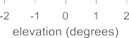
2.150 minimum to 2.450 maximum. This is to be achieved by switching on additional phased array elements as the steering angle increases. In addition to that, beam contours at nadir can be seen in Figure 2 [7]. Contours are given at -2, -4, -6, -10, -15 and -20 dB. Using a 2.50 beamwidth at elevation and at azimuth at nadir (1110 km) would yield a spot beam whose footprint would have a diameter of about 48 km at that distance. For the sake of simplicity, it is assumed that proposed system operates within a single cell.
The transmitting signals use a downlink signal. The downlink signal itself is 2 GHz wide and at X-band, from 10.7 to 12.7 GHz. However, if a terrestrial cellular network structure is to be replicated, we may assume that different cells from a single satellite will use a portion of that bandwidth. Satellites will create 7 beams as seen in Figure 1b, and each one is allocated equal bandwidths (nearly 250 MHz in each cell according to published documents), which yields a quasi-monostatic range resolution of approximately 0.6m.
![]()

Figure 2. Transmit beam contours at various scanning angles at nadir
SpaceX’s FCC application suggests their arrays will be forming beams with different frequencies.[3] The documents do not mention beamforming capabilities with a combined bandwidth. Therefore, it is inferred that multiplexing will be done using FDMA only. If there is a minimum of one active broadband user during measurements within the same cell as target, this already ensures target is illuminated. It is further assumed that modems will be active even in the absence of users. These modems will be actively engaging with satellites for session and network management and similar tasks. The intensity of the modem activities may be less than an active user, however the probability of having non-interleaved transmissions would increase with respect to number of subscribers. Finally, since there is only one user needed for illumination, theoretically the constellation could be “tricked” into illuminating a target by asking for service, but this is not in the scope of this study.
Power Budget estimation:
The power budget for detection is calculated and in addition, results obtained from Starlink are compared to those of GNSS-based system to gain an appreciation of the relative merits and drawbacks.
Passive Radar Parameters:
More than 250MHz bandwidth is assumed as returns from a single satellite cell. For the sake of simplicity, the size of both the reference antenna (for direct signal reception) and the radar antenna (for echo reception) is assumed to be 1 m2. This antenna surface area could also be included as a design parameter. At X-band, the beamwidth of such an antenna would be about
1.3 degrees. The remaining radar parameters for a Starlink-based and an equivalent GNSS-based radar system, can be seen in Table 1.
| Parameter (Notation) | GNSS | SpaceX |
| Centre Frequency (Fc) | 1.1765 GHz | 11.575 GHz |
| Bandwidth (BW) | 10.23 MHz | 250 MHz |
| Radar antenna height (hrx) | 1.5 m | 1.5 m |
| Antenna Effective Area (Arx) | 1 m2 | 1 m2 |
| Antenna beamwidth (θrx) | 13 degrees | 1.3 degrees |
| Antenna gain (Grx) | 22.9 dB | 42.7 dB |
| Noise temperature (Tn) | 300 K | 300 K |
| Ambient Noise (Pn) | -132.0 dB | -118.4 dB |
| Receiver Noise figure (Nf) | 1.4 dB | 1.4 dB |
| System losses (L) | 6 dB | 6 dB |
| Target RCS (σ) | 10 m2 | 10 m2 |
| Range resolution (Δrange) | 14.7m | 0.6m |
Table 1. Parameters for a Starlink-based and an equivalent GNSS-based radar system
SNR at reference antenna output
The EIRP (effective isotropic radiation power) at the Starlink antenna output and the Power Flux Density (PFD) near the ground can be found below in Table 2 [7]. The table shows that the transmit antenna array adjusts output power to ensure a PFD of -182 dBW/m2/Hz compared to -203.8 dBW/m2/Hz from its GNSS counterpart.
| Notation | Parameter | Starlink at Slant | Starlink at Nadir | GNSS |
| EIRP | Equivalent Isotropically Radiated Power at Satellite (dBW/Hz) | -47.1 | -50.13 | -46.68 |
| Rorbit | Distance to Earth (km) | 1574.58 | 1110.00 | 20200 |
| FSPL | Spreading loss (dB) | -134.94 | -131.90 | -157.1 |
| PFD | Power Flux Density at Ground (dB(W/m2/Hz)) | -182.02 | -182.02 | -203.8 |
Table 2. EIRP and PFD values
Using the aforementioned parameters, the SNR at the reference antenna output can be calculated as:
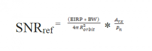
Based on the parameters set in Table 1 and Table 2, the SNR at the output of the reference antenna is around 20 dB. This means that purely from a SNR point of view, the direct signal can be used as a reference signal for matched filtering directly as in most passive radar systems. However, for an antenna with a beamwidth of 1.3 degrees, a satellite tracking array may be needed over the available dwell time on target.
SNR
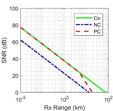
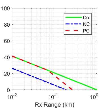
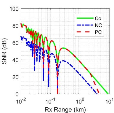
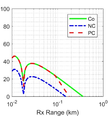
The SNR of a signal returned from two different target types, airborne and ground-based (or maritime) is calculated. The assumption for airborne targets is free-space propagation and for ground-based targets it is two-ray path (where multipath and clutter would also be present but are not considered in these first proof of concept calculations). The SNR at the output of a matched filter and an integration time of 1s is shown in Figure 3, based on the parameters of Table 2, for a hypothetical Starlink and GNSS-based radar. The figure assumes coherent (Co) and non-coherent (NC) integration, as well as the more pessimistic case (PC) which assumes that as the SNR for a single pulse goes below 0 dB, the signal processing gain from matched filtering will be deteriorated.
-
-
- (c)
-
-
-
- (d)
-
Figure 3 SNR after 1s integration (a) Starlink against airborne targets (b) Starlink against ground-targets (c) GNSS against airborne targets (d) GNSS against ground targets
The figure shows that setting a 12 dB SNR as the detection threshold, a coherent integration (best case) of 1s yields a maximum detection range for a 10m2 RCS airborne target of approximately 10km, while a purely non-coherent integration (worst case) brings this figure down to 2km. For a ground-based target where two-ray path propagation should be assumed, a target with the same RCS would be detected at a maximum range of approximately 4km for coherent and 1.5km for the worst case. An equivalent GNSS-based system would provide an equivalent 200m for the same airborne target, and approximately 10m for a ground-based target under best case conditions, which is two orders of magnitude less than Starlink.
Although this is a theoretical study, it gives us the perspective that even ‘commercial internet satellites’ can be used for encrypted message transfer and to track objects of various dimensions whenever required. Since the US military’s Starlink project is still at the beginning stage, major milestones are yet to be achieved. Satellite constellations like Starlink, have the potential to make conventional ASAT weapons obsolete owing to the nature and sheer size of its architecture besides enhancing war fighting capabilities.
Manickavasagam Thiruchitrambalam is a budding mechanical engineer with a keen interest in military aerospace developments.
REFERENCES:
- Sayin, Alp & Cherniakov, Mikhail & Antoniou, Michail. (2019). Passive radar using Starlink transmissions: A theoretical study. 1-7. 10.23919/IRS.2019.8768105. ↑
- M. Antoniou and M. Cherniakov, ‘GNSS-based passive radar’, in Real aperture array radar, imaging radar, and passive and multistatic radar, Edison, NJ: SciTech Publishing, an imprint of the IET, 2017, pp. 719–766. ↑
- FCC and Space Exploration Holdings, ‘FCC Application Listing SATLOA2016111500118’,INTERNATIONAL BUREAU FCC SELECTED APPLICATION LISTING BY FILE NUMBER REPORT WR07, 15-Nov-2016. [Online]. ↑
© Delhi Defence Review. Reproducing this content in full without permission is prohibited.


