


The Indian Space Research Organization (ISRO) has long sought to lower the cost of access to space. In keeping with this goal, ISRO embarked on the Reusable Launch Vehicle-Technology Demonstration (RLV-TD) Program more than decade ago. As part of the RLV-TD program, it has been developing various technologies that will serve as building blocks for a future Two-stage-to-orbit (TSTO) reusable launch vehicle. Importantly, these technologies are being developed in phases through a series of experimental flights. While the first flight of the RLV-TD, dubbed the ‘hypersonic flight experiment’ (HEX), was successfully executed on May 23, 2016, the stage is now set for the return flight experiment (REX) and scramjet propulsion experiment (SPEX) missions, respectively. LEX, in particular, is expected to be performed in the coming months.
Overall, the RLV -TD program aims to develop:
1. Hypersonic aero-thermodynamic design validation of winged-body vehicle
2. Evaluation of autonomous navigation, guidance, control and integrated flight management for said vehicle
3. Necessary infrastructure for design, analysis, simulation and testing for winged RLVs
4. Design and experimental flight experience of such vehicles with Thermal Protection Systems (TPS), hot structures, control surfaces and Reaction Control Systems (RCS)
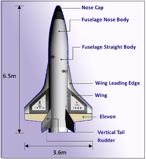
Figure 1: RLV-TD Vehicle Configuration
As such, HEX has already served to validate autonomous navigation, guidance and control (NGC), while also proving vehicle aerodynamics, thermal protection and mission management systems. Future RLV-TD flights will seek to validate landing and propulsion-related technologies in order to serve as a test-bed for a follow-on programme that aims to develop a much larger RLV. This RLV will feature a SC 500 semi-cryogenic engine as well as a cryogenic CE 50 engine giving it a semi-cryo fly-back booster and a cryogenic orbiter. It is expected to have the capacity of putting a payload of 10 tonnes (T) into Low Earth Orbit (LEO). Let us now take a deeper dive into the aerodynamic and thermal protection-related technologies developed as part of the RLV-TD programme and the challenges overcome therein. We will look at the development of sensing and guidance technologies related to the RLV-TD programme in a subsequent piece.
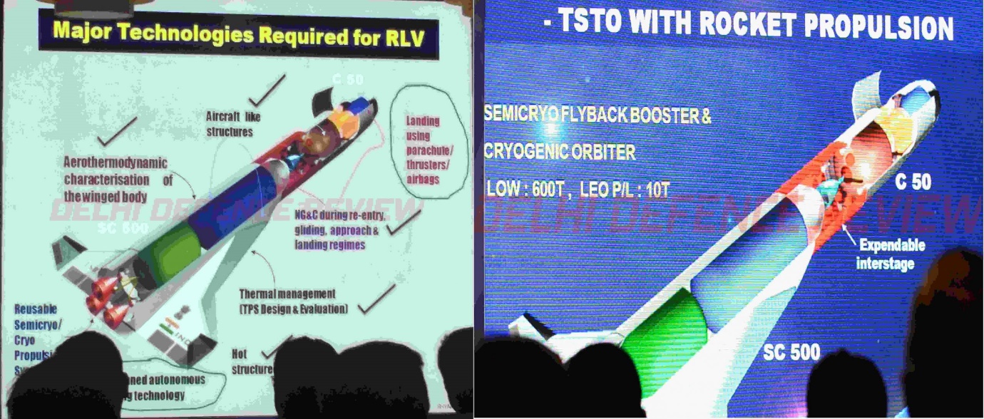
Figure 2: Technologies Required for RLV
The challenges faced by ISRO in the RLV-TD program are highlighted in Fig. 3 below.
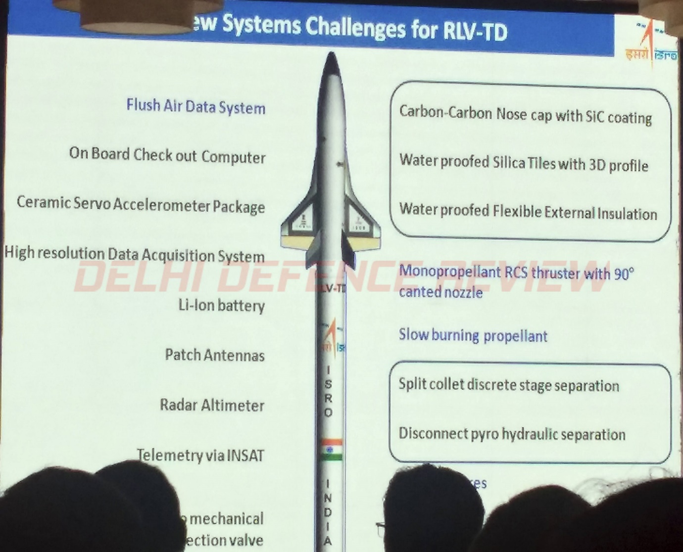
Figure 3: New Systems Challenges
Aerodynamics
The RLV-TD has a blunt ogive forebody followed by a D-section fuselage. The D-shaped portion was designed to ease application of Thermal Protection System (TPS) and to have a low-blended wing configuration to lower aerodynamic heating. The vehicle has a drooped nose to cater to visibility requirements making it easier to develop manned versions of the same design in the future. Initial designs which featured a single vertical tail were discarded due to a lack of rudder authority at high angle of attack (AoA) during the re-entry phase. A twin-canted vertical tail airfoil of double-wedge type with maximum thickness at 60 percent of chord was chosen which also doubles up as speed brakes and helps in pitch trimming(ruddervator). Flight control logic for pitch and roll-axes was complex due to twin canted tail rudders. The CSIR-NAL team which developed the control laws for the LCA Tejas provided assistance to the program.
The double-delta wing has an 80 leading edge strake angle and a 45 main wing leading edge angle. This delays the wing stall and reduces the centre of pressure movement over the operating range of Mach numbers. The wing has an aspect ratio of 2.16, 3 dihedral angle (wing tip section is at a higher level than the wing root section) and wingspan of 0.55 times the vehicle length. 12 reaction control system (RCS) thrusters were used for three-axis control during low dynamic pressure conditions. The pitch RCS thrusters were placed in the top and bottom surfaces of the aft fuselage, the yaw RCS thrusters were placed at the aft fuselage side panels and the roll RCS thrusters were placed in the top and bottom surfaces of the wing.
A solid booster had to be developed for HEX, since neither PSLV nor GSLV flights were available for this mission. This also meant, that unlike other countries which flew their vehicles within a launch vehicle payload shroud, RLV-TD had to be out in the open leading to aerodynamic challenges. A satellite along with ICGS Sagar & ICGS Samudra were employed for continuous telemetry during the mission. Validation of the aerodynamic design and ground based aerodynamic data generation procedure was one of the objectives of this Hypersonic Experiment (HEX) mission. In-house CFD software was one of the main sources of design and data generation apart from wind tunnel testing and application of engineering methods. Pressure measurements were made in the flight configuration over the fuselage, wing, vertical tail and rudder to carry out post-flight comparison.
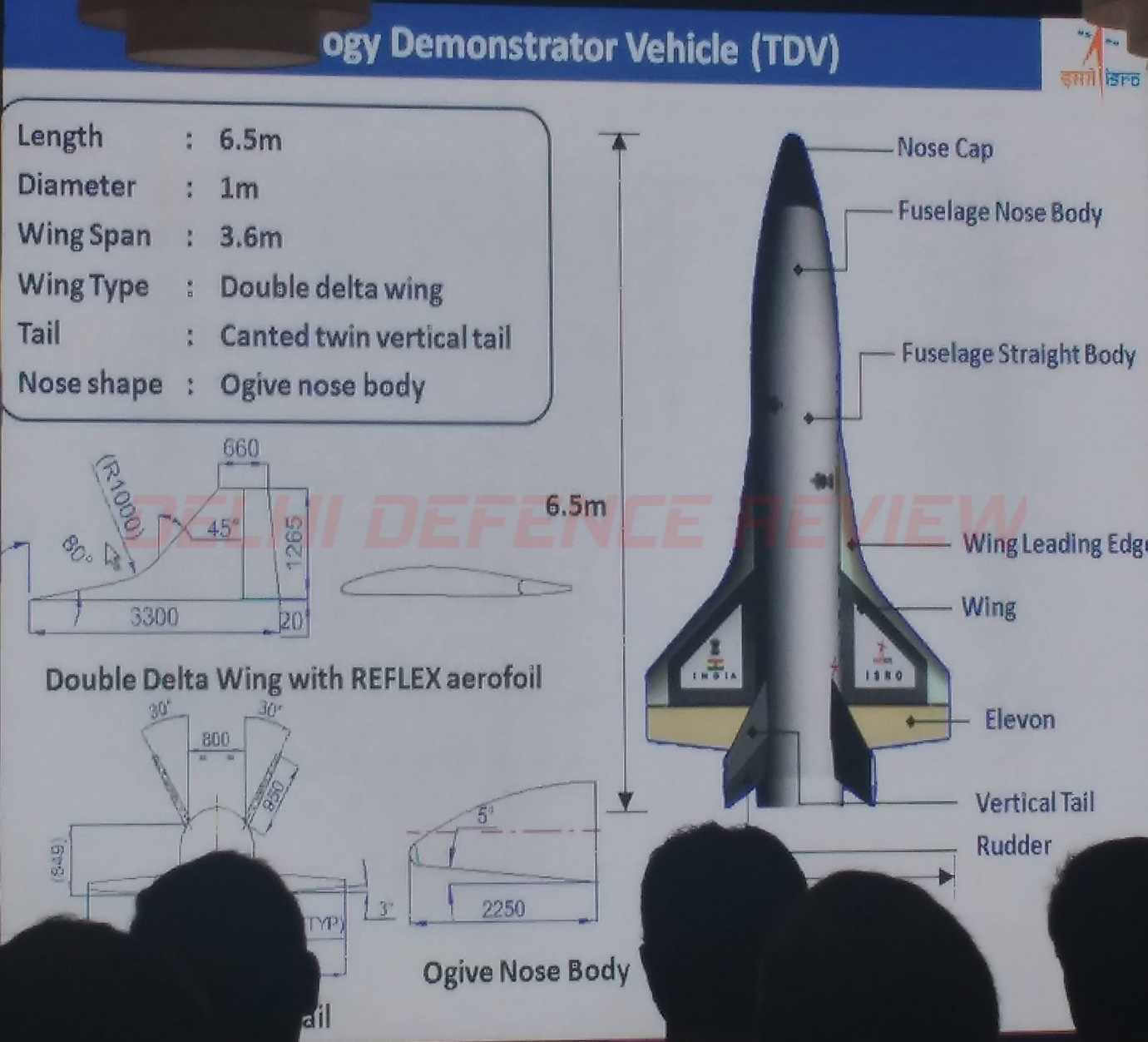 Figure 4: RLV-TD Dimensions
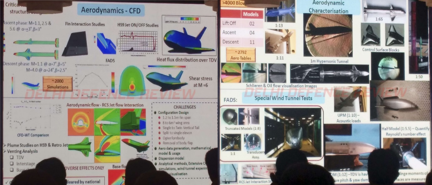 Figure 5: Aerodynamics
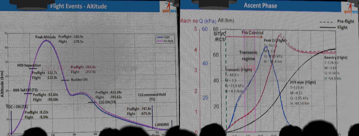
Figure 6: Altitude, Speed Charts
Thermal Protection Systems
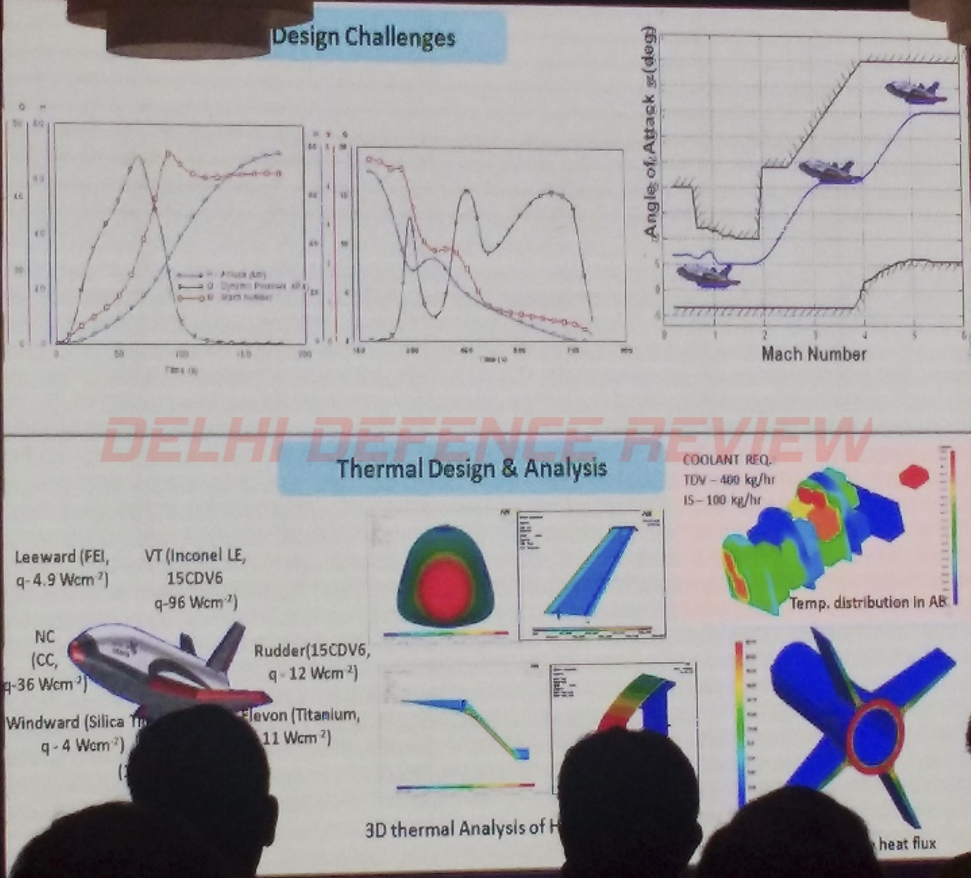
Figure 7: Thermal Protection Systems
The airframe of the RLV is made from Aluminium. Naturally, high speeds during re-entry of the vehicle into the Earth’s atmosphere results in extremely high temperatures on the surface of the RLV. This necessitates use of materials capable of withstanding such temperatures to protect the vehicle.
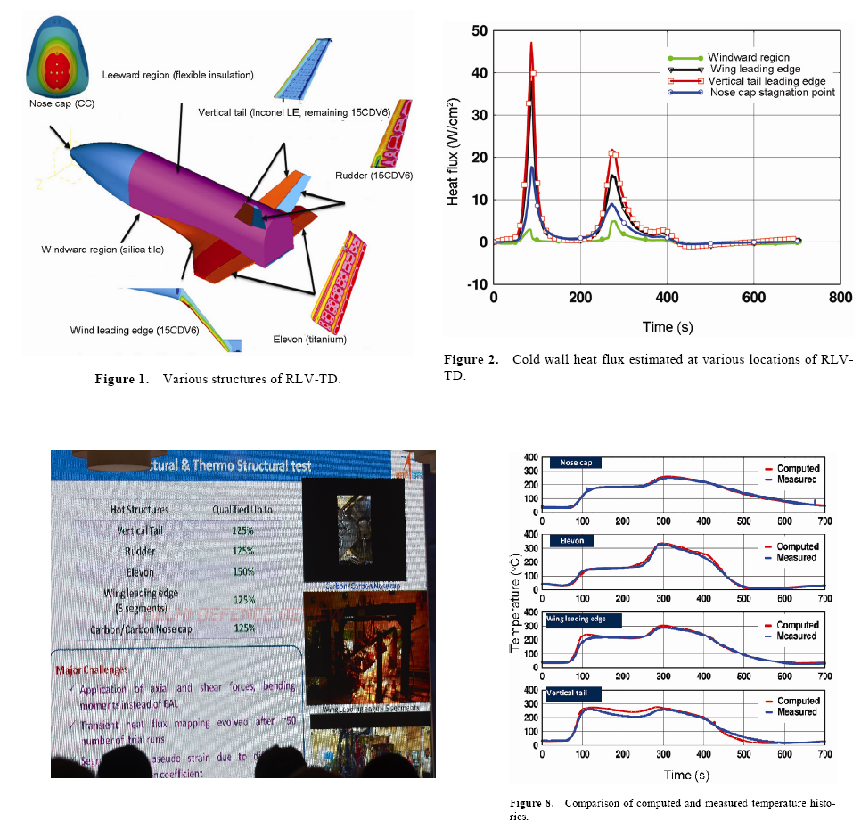
Figure 8: Thermal Challenges
Curvatures on the body of the RLV-TD necessitate the use of flexible thermal protection systems (TPS). The Aerothermal Simulation and Testing Division (ASTD) of Vikram Sarabhai Space Centre (VSSC), Thiruvananthapuram for RLV-TD HEX mission decided to use flexible external insulation (FEI), which has silica-cloth layers on either side with Cerablanket felt (density 128 kg/m3) sandwiched and stitched together using quartz thread (thickness of FEI is 15 mm). TPS system-design is required to generate the desired temperature gradient at the backwall by developing a configuration of FEI having a ceramic surface layer coating with high-emissivity and low-absorptivity.
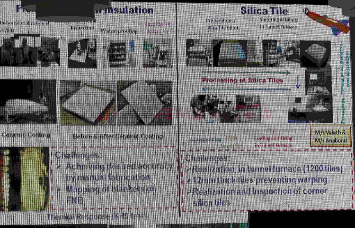
Figure 9: Thermal Protection Systems
Developing a binder that would help in utilising Silica for protection was a challenge. In-house efforts were made to select a suitable silica binder for this purpose and blankets with protection material were tested at NAL, Bengaluru followed by further testing using a non-destructive technique (NDT) method in VSSC. A room-temperature curable silica-based ceramic coating was developed which is compatible with silica or/and quartz fabric. The coating can be applied over FEI blankets either by spraying or brushing with minimum weight gain. Incidentally, this coating withstood a maximum heat flux of 4.8 W/cm2 during the KHS test.
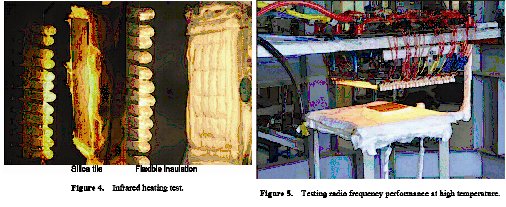
Figure 10: Thermal Protection Systems- Silica Tiles
Landing Experiment
The first test HEX validated the design and mission requirements. The subsequent landing experiment test is to validate autonomous landing. Landing is the critical phase of any winged body’s mission. The test will validate safe deployment of landing gear at the right time, aerodynamic design of the RLV-TD in close proximity to the ground, flight path selection and control laws implementation for flight control. The RLV-TD will be carried by a Mi-26 helicopter and then dropped to perform this test. Studies have been carried out to understand effect of rotor downwash as well as influence of ground effect during landing. The landing gear was supplied by Hindustan Aeronautics Ltd. The experiment will utilise the runway at Challakere Aeronautical Test Range, Karnataka. Following the landing experiment, an orbital insertion followed by de-orbital and landing and scramjet engine integration are planned.
Some of the above information and images were obtained from papers published in academic journals by ISRO.
© Delhi Defence Review. Reproducing this content in full without permission is prohibited.


