


With the Indian Air Force’s (IAF’s) MMRCA program getting serially delayed and recast more than once, there was a feeling in various quarters that the Tejas Mk2 design should perhaps evolve further than what was initially envisaged to provide an indigenous option for the IAF’s requirements. Thus, the IAF and the Aeronautical Development Agency (ADA) sat down to redefine the Tejas Mk2 with more elaborate modifications such that it could function as a medium weight fighter for ground attack roles while continuing to be nimble in the air to air (A2A) role. In fact, the version of the Tejas Mk2 currently envisaged has been rebadged as the Medium Weight Fighter or (MWF) and is being designed as a replacement for the Mirage 2000 with a view to surpassing its capabilities in almost every respect [13],[14].
The most eye-catching change is the addition of canards. Although, ADA had considered Light Combat Aircraft (LCA) configurations with canards as one the short-selected design concepts back in the 1980s itself, it decided to drop the canards after careful wind tunnel studies. At the time, the advantages offered by the canard configuration were deemed to be minor in comparison to the added complexities of having an extra control surface. After all, this was the first time that a Digital Fly-By-Wire (FBW) flight control system (FCS) was being designed for a fighter within India, let alone a highly unstable one. And SAAB’s experience with the Gripen in the 1990s has shown that this was a wise decision. Instead, ADA went with the iconic double delta wing with lower sweep inboard section.
However, now that a stable and robust flight control system (FCS) has already been designed, tested and validated, the addition of canards is an incremental development which ADA is confident of undertaking. The incorporation of canards also obviates the need to redesign the wing to cater to a shift in the center of lift (CoL) commensurate to a forward shift in the center of gravity (CG), which would invariably happen once the length of the fuselage is increased (more on this later). Instead, using the canards to move the center of lift forward while retaining the old wing seems like an attractive option, given that it also brings with it other aerodynamic advantages . The canards in MWF are positioned below the avionics bay cover, just behind the cockpit. They are in close-coupled configuration and are positioned slightly ahead and above the wing plane for optimal wing-canard interaction. The canards are set at a negative angle and have a slight dihedral angle. Close-coupled canards significantly affect wing aerodynamics on account of their favorable wing-canard interaction and increase lift produced by the wing considerably. Canards help stabilize the wing LE vortices for medium to high Angle of Attack (AoA) by delaying vortex breakdown. In addition, they produce significant lift themselves, further augmenting the total lift produced by the aircraft. Canards also help achieve better area ruling for reduced wave drag. In the air, they can act as extra control surfaces for pitch and directional control, and on the ground, as air-brakes during landing roll. In fact, for MWF, the canards will be used as pitch control surfaces and as air-brakes to reduce landing roll. In contrast, long coupled canards (as seen on the Eurofighter Typhoon or the Rockwell-MBB X-31) are only meant to be control surfaces and they neither contribute significantly to overall lift, nor do they interact strongly with the extant wing aerodynamics.
Canards add lift ahead of the CG, thus increasing requirement for trim force, which in the case of statically unstable tailless delta wings, is achieved by increased downward deflection of the elevons. But this also increases the lift produced by the wings, as the elevons act as flaps in this case. Consequently, with the addition of lift from the canard, increased lift by the wing due to favorable wing-canard interaction and an increase in lift on account of downward elevator deflection at trim, there is a significant increase in the total trim lift produced at any given angle of attack (AoA). As a result, a close-coupled canard delta aircraft can be trimmed at a lower AoA for an equivalent amount of lift as compared to a tailless delta without canards. This leads to lower trim drag and better lift to drag (L/D) ratio across the flight envelope.
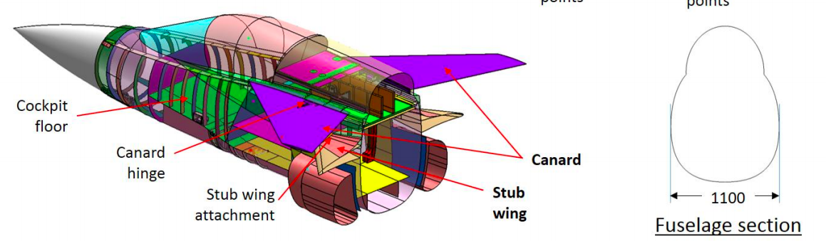
Figure 11: Front fuselage section showing Close-Coupled canards adopted for LCA Mk2 (MWF). The front fuselage is elongated by approximately 1.5m using two plugs and has increased height. The width remains same as that in MK1. [2].
In order to overcome the internal space constraints of the Tejas Mk1, MWF has been lengthened to 14.65 m, a sweet spot for a modern single engine multirole fighter. This allows the fighter enough internal volume for carrying the necessary systems, while having enough fuel for the range, endurance and performance requirements. This increase in length is achieved using two plugs, one in the nose, and another behind the cockpit. As both of these plugs are ahead of the wing, the CG shifts forward with respect to the CoL, thereby reducing the static stability margin, or in general terms, the maneuverability of an aircraft. As mentioned above, canards help to compensate for this by shifting the CoL forward proportionally to maintain the same static margin.
The canards also help smooth out the discontinuity in the area ruling curve ahead of the wing that exists for Mk1 (see this). By employing a canard and a fatter spine, MWF no longer needs as bulged a canopy as recommended by earlier studies. While those studies predicted a 6 percent supersonic wave drag resulting in a 20 percent improvement in transonic acceleration and 2 percent improvement in maximum speed, MWF is expected to exhibit even greater transonic and supersonic performance improvements given a near perfect area ruling through the changes such as the addition of a nose plug, elongated and fattened front fuselage, optimized canopy shape and rear fuselage. The canards lower the trim drag across the flight envelope, further enhancing overall aircraft performance. As a matter of fact, MWF is expected to have a top speed of Mach 1.8 in level flight with two close-combat missiles (CCMs), which is a 12.5 percent increase over its existing performance.
The shape of the canard was chosen after carefully studying a variety of geometries. Based on published computational fluid dynamic (CFD) studies, the leading edge (LE) sweep is expected to be equal to 50 degees. At this angle, the LE sweep provides an optimal increase in the lift coefficient with a smooth and desirable linear variation in the pitching coefficient at high AoA regimes. These CFD studies were then confirmed using extensive wind tunnel testing. A 1:10 scale wind tunnel model with canards was displayed at Aero India 2019, one of many configurations considered during the design phase. The canards typically have an adverse impact on the directional stability of an aircraft. The designers of MWF have taken measures to improve the directional stability by increasing the height of the tail fin and other measures. The increased height of tail fin is also necessitated by the elongated fuselage.
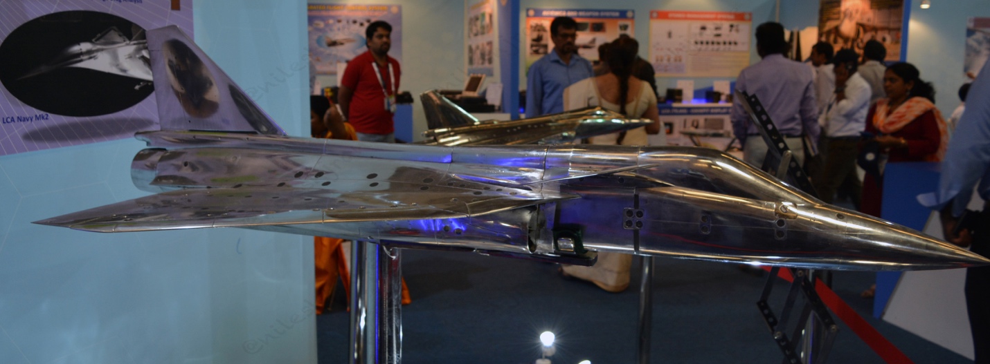
Figure 12: A 1:10 scale wind tunnel model of one of many canard configurations tested for MWF design studies.
In summary, a pair of closed coupled canards offer the following advantages to the Tejas Mk2 MWF:
- Maintain low wing loading by generating additional lift from canards
- Improved wing lift and better aerodynamic stability of wing vortices
- Reduced trim drag
- Better area ruling for reduction in transonic and supersonic wave drag
- Additional control surface for longitudinal control
- Allows considerable increase in fuselage length, which is one of the key changes helping MWF completely fulfill the IAF’s original Air Staff Qualitative Requirement (ASQR)
- Could be used as air brakes during landing reducing landing roll. Canards also help reduce Take-off distance (Short Take-Off and Landing capability)
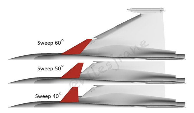
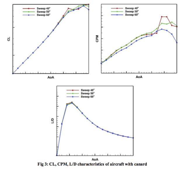
Figure 13: CFD Study showing effect of Canard LE sweep angle on overall aerodynamic performance of LCA. A canard with 50° sweep provides optimal lift increase and more desirable pitch moment characteristics in the high AoA regime [3].
As mentioned earlier, MWF retains the main wing from MK1 with minor modifications. It has the same iconic double delta wing featuring lower sweep angle for the inboard section. In a pure delta wing, the LE vortex, which constitutes a large portion of the total lift, starts forming right from the apex, the point where the wing LE attaches with the fuselage. The lower sweep on the inboard section results in the wing LE vortex forming slightly downstream of the apex. This pushes the CoL slightly aft-ward and helps bring down the static instability to a manageable range. This wing configuration also allows the designers to have a significantly larger wing area for the same LE sweep angle, length of fuselage and static instability margin. Figure 14 shows the blue outline of a pure delta wing which would need to have its apex downstream to maintain the same level of instability. In addition, the leading edge portion of the inboard section is lifted up a bit to provide the required clearance between the air intakes and the lower surface of the wing.
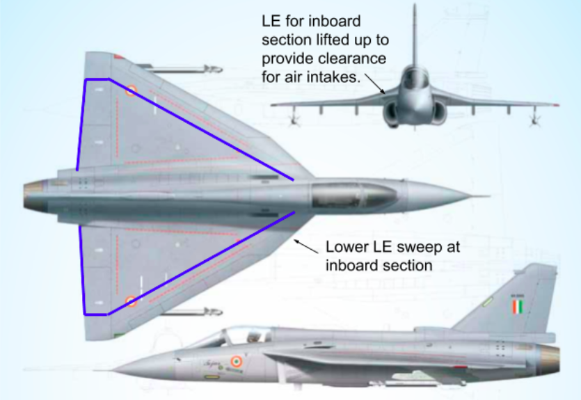
Figure 14: Schematic of LCA Mk1 from ADA Brochure. Blue line represents wing shape for pure Delta wing with same LE sweep of 62.5 degrees and fuselage length. Without the lower sweep inboard section, It would have to start slightly aft of current wing, to maintain same static instability margin.
The aerofoil design, dimensions and the upper interface with the fuselage also show no noticeable changes. On the other hand, the lower wing join shows better wing body blending which should lead to lower interference drag. The wings are moved outboard by 0.15 m each on either side. The wingtips are clipped further to allow the CCM pylons to be added at the wingtips (see figure 14). As a result of these changes, wingspan is increased slightly to 8.6 m. (see figure 13). The wing starts further aft of the cockpit due to the addition of the two fuselage plugs in the front fuselage section. On the other hand, the air intakes have been moved slightly aft, proportional only to the significantly smaller nose plug. This has resulted in a configuration where the intakes are no longer shielded by the wing, as is the case with the Mk1. However, the introduction of the canards should provide this shielding effect which helps straighten and redirect airflow to the intakes during high angle of attack manoeuvres, to some extent.
Recently, some Request for Information (RFI) documents were issued by HAL related to the manufacturing of assembly jigs for the fore, mid and aft fuselage sections of the MWF. Figure 15 shows a composite diagram obtained by joining three sections from the tenders.
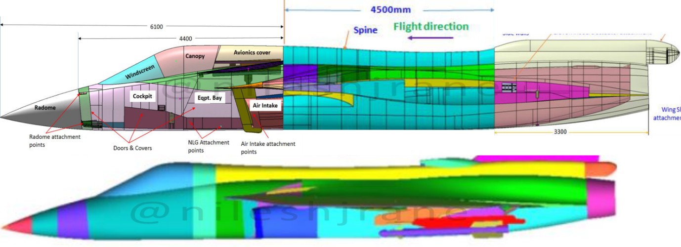
Figure 15: LCA Mk2 fuselage CAD images from reference [3]. Images of the three fuselage sections are scaled correctly and fused together.
Figure 16 shows the above composite CAD image with corrected scale and being compared to an image of the Tejas Mk1. This image allows us to compare the features of MWF with those of Mk1. As stated above, the length of the fuselage has been increased to 14.65 m. The spine is slightly more bulged for better area ruling. The vertical tail sits on a lifted spine, increasing total height by an estimated 0.25 m. The tail itself is expected to be extended by about 0.25 m due to an elongated fuselage. Hence the total height has increased to 4.86 m.
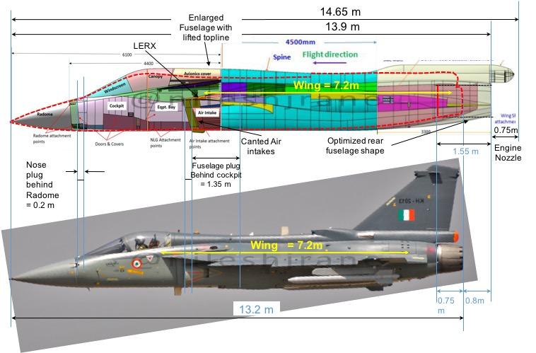
Figure 16: Comparison of LCA Mk2 (MWF) fuselage CAD image with LCA MK1. Red dotted profile of Mk1 is superimposed on MK2’s fuselage. Approximate measurements highlighting changes in the fuselage length and some key features.
A small strake or leading edge root extension (LERX) has been added ahead of the wing which extends till the point where the wing starts with respect to the cockpit in Mk1 (see Figure 17, side view, below the canards). LERX anchors the LE vortex for the inboard section of the wing which now comes under the influence of the canards. This has a positive impact on the aerodynamic stability of the vortices. The addition of LERX has a positive impact on the wing aerodynamics stability. Coupled with the canards, aerodynamic refinements, and enhanced engine power, the MWF is designed to reach the IAF’s Mk1 ASQR requirement of a sustained turn rate (STR) of 18 degrees per second. The splitter plates as well as the air intakes are canted backwards. The intakes also have a subtle sweep added to them. This is expected to result in optimal shock structure in the local vicinity which would reduce spillage drag at supersonic speeds and result in better intake performance. An improved intake cowl contours and the new 3-door auxiliary intake design will also be incorporated. All these modifications improve intake aerodynamics by improving pressure recovery and better uniformity of the flow at low speed, high Angle of Attack (AoA) regimes. This will lead to augmented thrust and reduced chances of engine stall. The low energy boundary layer flow separated by the splitter plate will be completely redirected under the fuselage now. The slot which redirects some of this air over the wing in MK1 is eliminated in MWF, as smooth flow over the wings behind the canards is desirable. Other drag reduction features in the aft fuselage as envisioned in the original Mk2 design can also be seen on the optimized fuselage of MWF.


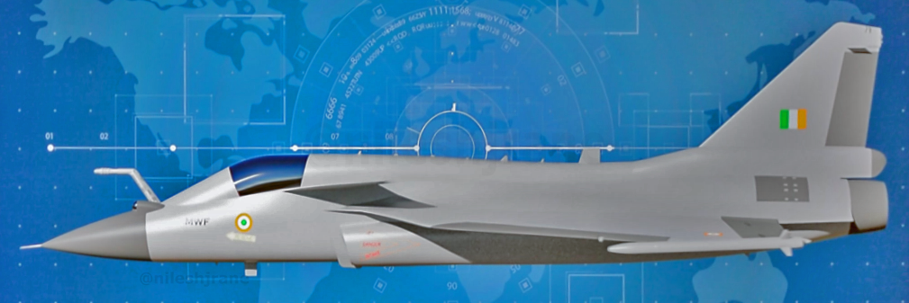
Figure 17: Medium Weight Fighter, front, rear and port-side views.
MWF will be a multirole aircraft capable of carrying R-73 (and possibly ASRAAM and Python 5) CCMs, Derby and Astra BVRs, 250 kg and 500 kg dumb and laser guided bombs, heavy precision glide bombs of standoff ranges, India’s New Generation Anti-Radiation Missile besides lightweight cruise missiles, including SCALP and Brahmos-NG. It will sport an active electronic scanned array (AESA) radar with an integral Unified Electronic Warfare Suite (UEWS) and a dual colour Missile Approach Warning System (MAWS) along with an upgraded glass cockpit with larger MFDs. The Digital Flight Control Computer hardware will be upgraded to the latest standard. Over the years, flight control actuators have been successfully indigenized. MWF will feature these Indian actuators, which is another significant achievement. It will also feature an enhanced Network Centric Warfare capability with seamless integration with various offensive and defensive systems of the Indian Armed Forces. With all these additional capabilities, the MWF represents a multi-fold increase in capability over the Mk1. Any future indigenously developed weapons such as Garuda, Garuthma, SFDR, Rudra-M etc.; sensors/avionics packages such as AESA Radars and some of the key fifth generation technologies such as flush sensors and antennas, radar absorbing materials, sensor fusion and so on will eventually find their way into MWF, keeping it relevant for a long time to come.
| Specification | LCA MK1 | LCA Mk2 | Mirage 2000 | Gripen E |
| Length | 13.2 m | 14.65 m | 14.36 m | 15.2 m |
| Height | 4.4 m | 4.86 m | 5.2 m | 4.5 m |
| Wingspan | 8.2 m | 8.5 m | 9.13 m | 8.6 m |
| Wing Area | 38.4 m2 | 38.4 m2 | 41 m2 | 31 m2 |
| Empty weight | 7040 kg | 7000 kg | 7500 kg | 8000 kg |
| Take-off Clean Weight | 10300 kg | 11,000* kg | – | – |
| Internal Fuel | 2400 kg | 3300 kg | 3200 kg | 3400 kg |
| Hard points | 7 + 1 | 11 | 9 | 9 + 1 |
| Max Take Off Weight | 13,500 kg | 17,500 kg | 17500 kg | 16500 kg |
| Max payload capacity | 3910 kg | 6500 kg | 6300 kg | 6000 kg |
| Engine | F404-IN20 | F414-INS6 | M53-P20 | F414 |
| Max Thrust | 84kN | 98kN | 98kN | 98kN |
| Max Speed | 1.6M | 1.8M | 2.2M | 2.0M |
| G limits | +8/-3.5 | +9/-3.2 | – | +9/-3 |
| Ferry Range | 1750 km | 3500* km | 3335 km | 4000 km |
Table 1: LCA MK2 (MWF) specifications compared with those of LCA MK1, Mirage 2000 and Gripen E (* estimated number).
The expected features of MWF are listed in Table 1 above and compared to that of Tejas Mk1, Mirage 2000 and Gripen E. The payload capacity of MWF will be 6.5 tons as compared to the Mk1’s 3.9 tons. To carry this increased payload, the number of pylons have been increased from 8 to 11. The gun has been moved to a shoulder mounted position which has freed up space below the right intake for an additional pylon. Each wing also features four stations instead of the current three. ADA is also developing multi-rack pylons for carrying two BVR AAMs. The addition of the nose plug has also afforded space for an infra-red search and track (IRST) system, and the fuselage plugs facilitate the availability of space for an internal self-protection jammer and significantly higher internal fuel. Cumulatively, these changes not only enhance mission capability of the aircraft, but add greatly to its flexibility. What is more, MWF brochure indicates that all this additional capability comes with no additional empty weight. This optimistic estimate probably arises from the optimization of airframe structures in the second design iteration of LCA. Realistically though, some increase in the empty weight can be expected. Even with some weight gain, MWF will retain its exceptionally low wing loading. With this low wing loading, increased T/W ratio owing to its more powerful engines and optimized airframe for wave drag and enhanced manoeuvrability on account of canards, MWF is expected to achieve all the performance parameters specified by 1985 ASQR.
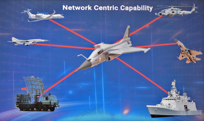
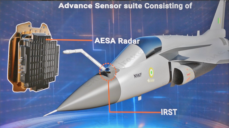
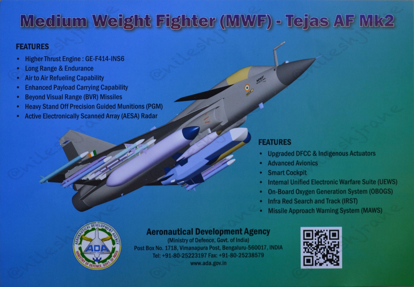
Figure 18: Schematics published by ADA during Aero India 2019, showing various aspects of the Medium Weight Fighter’s Capabilities and features.
While ADA is busy with the design of MWF, HAL has already embarked on design and development of manufacturing jigs for MWF. This is an indication that the MWF design is already in an advance stage. Metal cutting for first MWF is expected in a few months. ADA is sanguine on first flight of MWF by end of 2021 or early 2022. A total of four prototype aircrafts are planned for the flight test program. However, these 4 aircrafts will be production standard aircrafts, unlike LCA MK1 which saw the evolution through technology demonstrator, prototype vehicle and limited series production stages before serial production was taken up. This an indication of the increased maturity in the team vis-à-vis design and manufacturing capability as well as project management. In other words, the production of MWF will continue in the background as the flight test program is put through its paces.
On the manufacturing side, ADA and HAL are working on bringing next generation processes and technologies in the manufacturing of the MWF. Currently, the entire LCA Mk1 airframe structure is first assembled and then all LRUs, electric looms, piping and so on are fitted in an equipping stage. This is a serial process which takes up a significant amount of time. Instead, for MWF, ADA is working on a modular concept in which electric looms, piping, and connectors are terminated at sub-assembly interfaces with appropriate interconnectors [18]. All the major sub-assemblies namely the three fuselage sections, wings, and the fin are also being designed with this modular approach in mind. Four Tier-1 suppliers have already been identified to take up these high-level sub-assemblies. These high level sub-assemblies are further subdivided into modular sub-sub-assemblies and so on. These, in turn which will be outsourced to Tier-2/3 suppliers. The assembly will take place using a ‘jig-less’ assembly process [3]. In this approach, the jigs are modular by design and have more versatility to adapt to any changes in the build standard of the aircraft. Such jigs can also be repurposed for a completely different assembly process in the future when required. Since the jig-less assembly approach does away with the conventional locating function, more automated operations such as robotic holes drilling are expected to be introduced in the assembly process. This approach could enable the Tier-1 suppliers to supply fully equipped sub-assembly modules to HAL. HAL can then simply connect these sub-assemblies using the interconnectors to quickly arrive at the final product, significantly reducing the final assembly time. With all these changes, HAL is confident of producing MWF at the rate of 24 aircraft per year from the currently existing two assembly lines. As of today, the Indian Air Force has given a letter of intent for 200 MWF. IAF is planning to replace its medium weight Mirage 2000, Jaguars and MiG29 fleets with MWF, in the coming decade.
Every successful fighter aircraft till date has evolved over many tranches and iterations to reach its final optimized version. The process of development itself leads to an increase in the knowledge and confidence of the designers and the associated manufacturing group. This allows the shortening of development time of not only the next iteration of the aircraft, but also for next generation aircraft as well. The Tejas story is no exception to this fundamental fact and on its shoulders stand the development of India’s future generation of fighter aircraft. Therefore, the evolution of the Tejas can rightly be called the evolution of India’s fighter aircraft industry.
References:
- https://www.livefistdefence.com/2011/01/model-lca-mk2-at-aero-india.html
- HAL RFI documents for LCA Mk2 fuselage sections, obtained from HAL Website.
- “An assessment of effects of Canard Sweep angle on the Longitudinal Aerodynamics of Delta wing aircraft”, 19th CFD Symposium, Bangalore, 2017.
- “Influence of Canopy shape on the supersonic drag of a generic Fighter Aircraft”, 17th Annual CFD Symposium, Bangalore, India, 2015.
- “Aerodynamic characteristics of a Generic Fighter aircraft with Air-to-Air missiles carried at Underwing station vis-a-vis Wing Tip”, 19th CFD Symposium, Bangalore, 2017.
- “Effect of arrangement of weapons on Zero lift drag of an Aircraft”, 18th Annual CFD Symposium, Bangalore, India, 2016.
- “CFD studies of a Supersonic drop tank for a generic fighter aircraft”, 17th Annual CFD Symposium, Bangalore, India, 2015.
- “CFD studies with nose chine and fuselage strake on a generic fighter aircraft”, 18th Annual CFD Symposium, Bangalore, India, 2016.
- “Design of fuel tank for a generic fighter aircraft constrained by its influence on neighboring store”, 18th Annual CFD Symposium, Bangalore, India, 2016.
- Aft body optimization of a generic fighter aircraft for supersonic drag reduction”, 18th Annual CFD Symposium, Bangalore, India, 2016.
- “Intake Performance studies for a generic fighter aircraft configuration”, 18th Annual CFD Symposium, Bangalore, India, 2016.
- “The LCA was designed to replace the MiG-21 aircraft, whereas the Mk-2 is being designed to replace the Mirage 2000,” Dr Girish Deodhar, programme director of ADA told ET. “It is being redesignated as a medium weight fighter.” https://economictimes.indiatimes.com/news/defence/tejas-mk-2-is-a-medium-weight-fighter/articleshow/64214939.cms
- ‘It is expected to have a maximum take-off weight of 17.5 tonnes with an improvement of over 85% in weapons and payload carrying capacity to that of Tejas, light combat aircraft (LCA)’. https://economictimes.indiatimes.com/news/defence/tejas-mk-2-is-a-medium-weight-fighter/articleshow/64214939.cms
- Kota Harinarayana – “I believe it would have far superior range and capabilities than the Mirage 2000.” From interview in Aeromag Asia, May-June 2018, Vol12, issue3
- https://delhidefencereview.com/2018/02/26/single-engine-fighter-cancellation-provides-an-opening-for-tejas-mk-2/amp/?__twitter_impression=true
- https://en.wikipedia.org/wiki/Dassault_Mirage_2000#Specifications_(Mirage_2000)
- https://en.wikipedia.org/wiki/Saab_JAS_39_Gripen#Specifications
- “Aircraft Performance Improvements-A Practical Approach”, S.K. Jebakumar, DRDO Science Spectrum, March 2009.
- “Effect of Arrangement of Weapons on Zero-Lift Drag of an Aircraft”, 18th Annual CFD Symposium, August 10-11, 2016.
© Delhi Defence Review. Reproducing this content in full without permission is prohibited.


